Synchronous Chip Sealer Instruction Manual
SPV Asphalt Chip Sealer User Manual
SPV Special Purpose Vehicle Co., Ltd. Road Maintenance Vehicle Professional Factory (China ● Hubei)
I. Preface
Dear User,
Please read this user manual carefully before use.
Thank you for your trust and recognition of the SPV brand, and for choosing the SPV Asphalt Chip Sealer. This manual introduces the performance parameters, maintenance, adjustments, and common troubleshooting for the SPV Asphalt Chip Sealer. 1
All relevant personnel should regularly read and make full use of this manual and other accompanying maintenance and operation manuals to keep the vehicle in good condition. This manual will help you operate this machine safely and correctly, and includes functional descriptions of important components and systems.
To prevent misunderstandings, this manual uses certain technical terms. Only qualified and trained personnel are permitted to operate this machine. 2
This manual and local safety regulations must always be observed. 3
Using this manual helps you quickly familiarize yourself with this machine and avoid malfunctions caused by improper operation. Adhering to this manual can improve the reliability of this machine, extend its service life, and reduce maintenance costs and time. 4
For any unclear points regarding the use, maintenance, and upkeep of the vehicle chassis, please refer to the original factory’s “User Manual.” Esteemed customers are requested to carefully read and strictly follow the instructions for operating and maintaining this SPV Asphalt Chip Sealer. 5
To meet the needs of different users, products are constantly being improved. If the content of this manual does not match your product, the actual product shall prevail. Please feel free to call our company for consultation; we will serve you enthusiastically. 6
We welcome your valuable suggestions for our equipment to provide you with better service! 7
Safety Warning Symbol Description
This safety warning symbol identifies important safety information in the manual. When you see this warning symbol, you should read the following information carefully, strictly adhere to it, and inform other operators. 8
We declare that installing and using parts or special equipment on this machine that have not been tested and approved by the manufacturer may affect the machine’s performance or even lead to safety hazards. We are not responsible for any damage caused thereby! Please ask your supervisor for the operation manual! Please keep this manual in an easily accessible place. This manual is part of this machine. 9
Our company reserves the right to continuously revise the content of the “Product User Manual” with technical improvements. We will not give further notice of changes, and we hope all users understand. 10
Safety Warning
- Due to the high surface temperature of various asphalt working devices and pipelines during the operation of the asphalt chip sealer, please wear work clothes, gloves, and protective caps before working to avoid burns. 11
- For the first use of a new vehicle, only 50% of the rated asphalt capacity (less than 4 tons) is allowed. 12
- Before adding high-temperature hot asphalt, the water in the tank must be completely cleaned; otherwise, high-temperature hot asphalt will expand violently and spray out upon contact with cold water, leading to danger. 13
- After using emulsified asphalt, if switching to high-temperature hot asphalt, all emulsified asphalt in the tank must be completely cleaned; otherwise, there will be danger. [For the first tank of asphalt, only 50% of the rated capacity (less than 4 tons) is allowed.] 14
- After using hot asphalt, if switching to emulsified asphalt, all residual asphalt in the asphalt pump, pipelines, and tank must be completely cleaned; otherwise, it cannot be used normally. 15
- During transportation and spraying, standing on the rear working platform of the chip sealer is strictly prohibited. 16
- After adding high-temperature hot asphalt, for safety, non-operators must stay at least 5 meters away from the asphalt distributor. 17
- To achieve satisfactory spraying quality, the added asphalt must reach the following temperatures: ordinary heavy-duty road hot asphalt above 160℃; SBS, SBR modified hot asphalt above 185℃; rubber asphalt above 200℃. SBS, SBR modified emulsified asphalt between 65-85℃. 18
- The allowable operating temperature for heat transfer oil is ≤250℃. 19
- When using emulsified asphalt, sediments at the bottom of the storage tank are prohibited from being added to the synchronous chip sealer; otherwise, it cannot be used. 20
- If the asphalt pump is stuck, do not force it to start. It must be heated and loosened before it can work. 21
- After construction, the spray arm should be folded and raised to the highest position, then secured with a safety hook. 22
- When engaging or disengaging the PTO, the vehicle engine must be turned off; otherwise, the PTO or the vehicle’s transmission will be damaged. 23
- During transportation, the PTO must be disengaged, the controller turned off, and inlet/outlet valves closed. The heat transfer oil pump must be stopped. Using the burner while driving is strictly prohibited; otherwise, safety accidents will occur. 24
- During transportation, the main switch of the working system’s air source must be closed. 25
- At the end of a day’s work, any remaining asphalt in the tank must be drained. 26
- The vehicle must undergo its “first maintenance” at an authorized chassis service station within 2500 KM of travel; otherwise, the chassis manufacturer will not provide a warranty. 27
- As national vehicle regulations are constantly updated, our company advises customers to apply for vehicle license plates within half a month of purchasing a new vehicle. 28
- The handheld spray gun cannot be used to spray high-temperature hot asphalt; it can only spray emulsified asphalt. Using the handheld spray gun to spray asphalt above 80 degrees Celsius will cause personal burns, and our company will not be responsible for any casualties resulting from this. 29
- When performing maintenance under the vehicle or parking for an extended period on a slope, ensure the vehicle engine is off and the handbrake is engaged. Additionally, place chocks or stones under the tires to prevent the vehicle from rolling. 30
II. Product Introduction
2.1 Overview
Asphalt synchronous chip sealing is a process where specialized equipment simultaneously applies chips and binder material onto the road surface. Under natural compaction, this forms an asphalt chip wear layer that protects the original pavement. This sealed surface enhances the waterproofing and anti-skid properties of the original road surface. 31
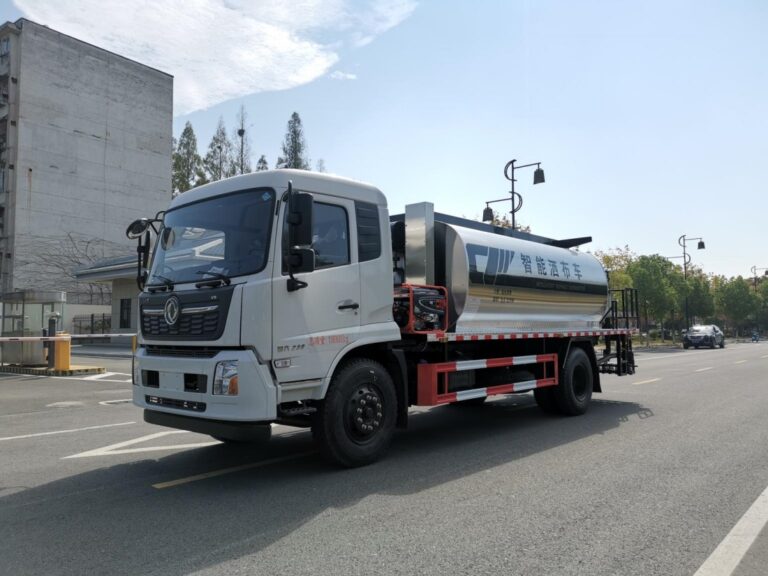
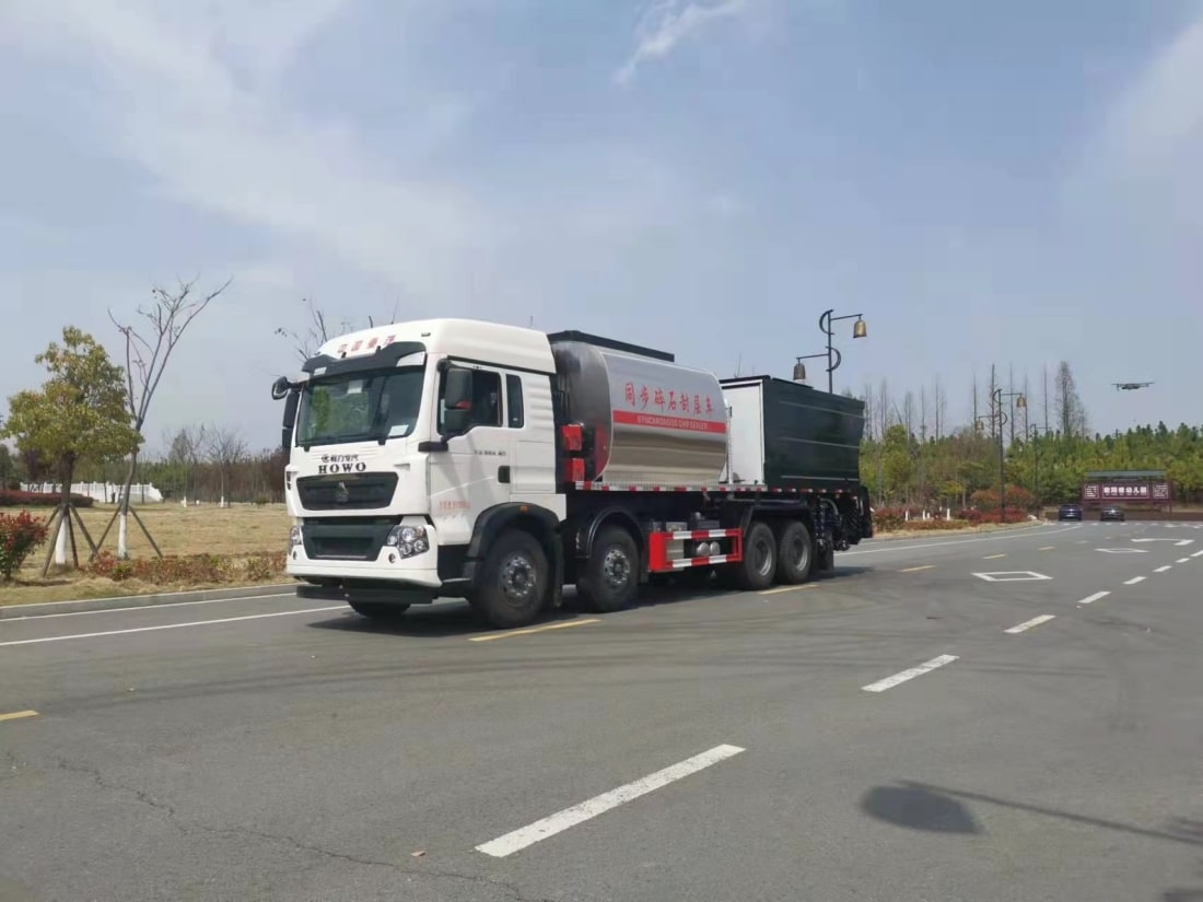
The SPV Asphalt Chip Sealer is a specialized machine developed by our company for asphalt pavement construction and maintenance. It can be widely used for the transportation and distribution of high-temperature liquid asphalt, emulsified asphalt, and modified asphalt. Its simple process, wide application range, and low cost make it popular among road professionals. 32
2.2 Application Scope of Asphalt Synchronous Chip Sealer
Asphalt synchronous chip sealing is used in chip sealing processes for highway surfaces, bridge deck waterproofing, and lower sealing layers. It can be used for interlayer treatment and mid-term maintenance construction on high-grade highways, and also directly for surfacing on rural roads with light traffic and some industrial park roads. In China, due to the continuous increase in traffic volume in recent years and severe vehicle overloading, pavement damage occurs prematurely. Using asphalt synchronous chip sealing technology for pavement maintenance is one of the most economical and feasible methods to extend pavement life, and it is a common maintenance method in developed countries in Europe and America. For rural roads with light traffic and some industrial park roads, directly using chip sealing for surfacing also yields excellent results. 33
2.3 Advantages of SPV Asphalt Synchronous Chip Sealer
2.3.1 The greatest advantage of asphalt synchronous chip sealing is that it shortens the interval between binder spraying and aggregate spreading, increasing the coverage area of aggregate particles by the binder. This ensures a stable proportional relationship between them, allowing the asphalt and aggregate to bond firmly and achieve a “root-and-branch” effect. This is particularly evident in low-temperature construction compared to separate chip sealing (i.e., asphalt distributor + chip spreader). Secondly, asphalt chip sealing improves operational efficiency, reduces equipment configuration, and lowers construction costs. After asphalt pavement is treated with asphalt chip sealing, the road surface gains excellent anti-skid and anti-seepage properties, effectively treating pavement issues such as oil deficiency, aggregate loss, minor alligator cracking, rutting, and settlement. It is primarily used for preventive and restorative maintenance of roads. This new maintenance technology can be applied to both highways and ordinary roads. 34
2.3.2 After lower layer construction, asphalt synchronous chip sealing provides effective waterproofing, protecting the subgrade from freeze-thaw damage. The upper and lower layers are well bonded during asphalt-aggregate paving. Traffic can be appropriately opened to allow vehicle compaction, ensuring the subgrade’s safety through winter. 35
2.3.3 Asphalt chip sealing construction period is short. The shortened construction period allows for quick traffic opening and rapid road maintenance, ensuring normal road operation. 36
2.3.4 When used in pavement maintenance, asphalt chip sealing saves labor and materials compared to hot-mix overlay methods, significantly reducing costs. 37
2.3.5 The SPV asphalt synchronous chip sealer is independently developed and designed by the SPV Special Purpose Vehicle Co., Ltd. Road and Municipal Maintenance Professional Vehicle Factory. It features simple operation, high automation, and uniform spreading. Combining the characteristics of China’s expressways, it increases the material bin capacity, allows for larger single-operation areas, and serves as a replacement product for segmented chip sealers and imported chip sealers. Based on feedback from actual engineering construction of the original product, the new product has been upgraded and improved, making operation simpler, more user-friendly, the product more applicable, and performance more reliable. 38
2.3.6 Asphalt distribution control can be completed not only in the driver’s cabin but also on the rear operation platform at the back of the vehicle. 39
2.3.7 The vehicle’s automatic control system can measure vehicle speed and automatically calculate the asphalt pump’s RPM based on the input spraying volume, spraying width, and asphalt type, and then automatically adjust the asphalt pump’s speed through the system. 40
2.3.8 The heating system employs imported Italian dual burners with automatic ignition and temperature control, characterized by fast heating and short heating times. The on-board rapid heating system (1-15℃/h) improves heating efficiency and reduces auxiliary construction time, ensuring the spraying temperature. 41
2.3.9 Utilizing internationally advanced high-viscosity asphalt pumps, external asphalt can be pumped into the tank for “self-suction,” and asphalt can also be pumped out of the tank for “self-discharge.” 42
2.3.10 Key components of the entire machine (such as hydraulic pumps, hydraulic motors, asphalt pumps, proportional valves, and automatic control systems) all use internationally renowned components to ensure the reliability of the entire machine and extend its service life. 43
2.3.11 The asphalt spray arm adopts a three-section folding structure, allowing for dual spraying when extended. Extending the spray arm left and right can widen the spraying range and effectively avoid obstacles. 44
2.3.12 The manual spraying function allows asphalt to be sprayed through a handheld spray gun, offering flexibility and convenience for small-area and corner construction. Connect the handheld spray gun, open the main oil outlet valve, open the pump-out valve, open the return oil valve, and adjust the pressure of the spray gun by varying the opening of the return oil valve. 45
2.3.13 The interior of the asphalt tank is equipped with a sedimentation drainage groove. 46
2.3.14 A good insulation layer ensures a static insulation performance index of ≤12℃/8 hours, and it is corrosion-resistant and durable. 47
2.4 Performance Features of SPV Asphalt Synchronous Chip Sealer
2.4.1 The SPV Asphalt Chip Sealer adopts chassis from Sinotruk Howo, Shaanxi Automobile, and other brands, offering comfortable operation and high reliability. 48
2.4.2 It uses an internally lifting aggregate bin, with a low lifting height, convenient for construction in culverts and under bridges, offering strong construction adaptability. The low height of the bin makes loading easy. 49
2.4.3 The spray arm has a spraying width of 4 meters. The asphalt spraying system features three-section horizontal folding, enabling dual spraying, and the folding operation of the spray arm is convenient. The spray arm is equipped with a heat transfer oil heating pipe to ensure unobstructed flow of the spraying medium. Nozzle opening and closing are controlled by nozzle air cylinders. The connection between the nozzle air cylinders and the spray arm is detachable for easy maintenance and replacement. Spraying is efficient and convenient, and working performance is safe and reliable. 50
2.4.4 When spraying asphalt, based on construction conditions, the computer can control automatic spraying by the spray arm nozzles or manual spraying with a handheld spray gun (Special reminder: The handheld spray gun cannot spray hot asphalt, only emulsified asphalt), allowing free selection. The intelligent spraying volume is precisely controlled by the computer. The asphalt pump and pipeline system use heat transfer oil for heating and insulation, preventing blockages in pipelines and nozzles. 51
2.4.5 The intelligent asphalt distributor control system uses electronic detection of vehicle speed and computer control of the asphalt pump’s rotation speed. By simply setting the asphalt distribution parameters per square meter, the construction spraying can be completed automatically, and the distribution volume is not affected by vehicle speed. The intelligent system has two control systems: one located in the driver’s cabin with a touch screen control, and the other located on the rear operation console with manual toggle switch control. Sensors detect asphalt and heat transfer oil temperatures to achieve automatic heating and insulation. 52
III. Main Structure and Working Principle
3.1 Main Structure
The product mainly consists of the chassis, asphalt tank, aggregate bin, asphalt spraying unit, chip spreading unit, chassis PTO unit, spreading mechanism unit, electrical control unit, hydraulic system, and heating system. 53
3.2 Working Principle
The asphalt chip sealer has three functions: synchronous chip sealing, independent asphalt spraying, and independent chip spreading. 54
Required Process or Conditions: The PTO must be engaged when the engine is off and there is sufficient air pressure. 55
The asphalt chip sealer is equipped with a chassis PTO system and a hydraulic system. The binder material is delivered to the spray nozzles through pipelines. After the aggregate bin is lifted, the chips fall automatically by gravity, are discharged by the roller, then fall into the distribution plate, and are then evenly spread by the spreading plate. Operation is simple, with PLC automatic control of spraying/spreading. The binder material and chips are synchronously sprayed/spread onto the road surface. Under natural vehicle compaction, an asphalt chip wear layer is formed, protecting the original road surface. 56
IV. Precautions Before Operation
4.1 Power Take-Off (PTO) Unit
Daily check the PTO housing for gear oil leakage. If there is leakage, replace the seals promptly and add gear oil until it reaches the middle of the dipstick. 57
4.2 Hydraulic System
4.2.1 Hydraulic Oil Inspection
Daily check the hydraulic oil level. If insufficient, replenish promptly until it reaches the middle of the dipstick. 58
4.2.2 Hydraulic Pipeline Inspection
Check the hydraulic system for any leaks, mainly at all joints. 59
4.3 Electrical Control System
Check that all control switches are in the “off” or neutral position. Check for any loose control switches. 60
4.4 Heat Transfer Oil Line Inspection
Check if the heat transfer oil level is normal. Check all pipeline joints and valves for any leaks. 61
4.5 Asphalt Pipeline Inspection
Check if the asphalt filter is clean. Check if the pipeline flange connection bolts are loose. 62
4.6 Chassis Inspection
Check if the engine oil level is normal; if the coolant is sufficient; if the brakes are effective; if all indicator lights are normal; if the tires have cracks and if the air pressure is normal; if the horn is working normally. 63
V. Operation Console Function Description
5.1 Front Operation Console Function Description and Operation Steps
5.1.1 Front Operation Console Function Description
| No. | Name | Function |
| 1 | Main Power Switch | Controls the power supply to the entire vehicle’s operating system. |
| 2 | PTO Switch | PTO control switch. For full-power PTO, the engine must be turned off when engaging. For non-full-power PTO, the clutch must be pressed. |
| 3 | Work Status Switch | “Synchronous” means asphalt and chips are used simultaneously. “Asphalt” means asphalt spraying only. “Chips” means chip spreading only. |
| 4 | Operation Status | Controls the start and stop of spraying from the asphalt circulation spray arm. |
| 5 | Nozzle Left | Adjusts the spraying width by increasing or decreasing from the left side of the spray arm. |
| 6 | Nozzle Right | Controls the spraying width by increasing or decreasing from the right side of the spray arm. |
| 7 | Nozzle Distribution | When asphalt spraying width is less than 4 meters, controls the spraying position from left to right, right to left, or from the center outwards. Used in conjunction with the “Nozzle Left” and “Nozzle Right” toggle switches to set the spraying position. |
| 8 | Hopper Lift Switch | Controls the raising and lowering of the aggregate bin. |
| 9 | Warning Light Switch | Working width lights on both sides of the rear aggregate bin. |
Note:
- The heat transfer oil pump can operate when the generator is generating power (when hydraulically driven, the heat transfer oil pump switch is located on the display screen). 64
- The hydraulic oil cooler automatically operates when the PTO switch is turned on. 65
5.1.2 Front Operation Console Operation Steps
Turn on the main power switch of the display to enter the display’s working interface; turn on the inverter power. 66
Click the “Start” button on the display interface to enter the working interface. 67
Engage the PTO, start the vehicle engine, turn on the heat transfer oil pump switch, and click the “Upper Burner” or “Lower Burner” button on the display interface to heat the asphalt in the asphalt tank. Wait for the asphalt to heat up to the set temperature. [Note: The upper burner heats the heat transfer oil, and the lower burner heats the asphalt. Do not use the lower burner if the asphalt level in the tank is below the lower combustion chamber, as this will damage the equipment and cause safety accidents.] 68
When the asphalt and heat transfer oil reach the set temperature, select the working status, open the oil outlet valve, set the operating status to “Ready,” and after the asphalt pump speed stabilizes, unfold the asphalt spray arm and aggregate diverter plate to begin spraying. (If the asphalt pump still cannot rotate, set the operating status to “Stop” and continue heating the heat transfer oil.) 69
Adjust the “Nozzle Distribution Switch,” “Nozzle Left Switch,” and “Nozzle Right” switch according to the spraying width and direction. 70
Adjust the “Work Status” switch: if asphalt and aggregate are to be sprayed simultaneously, toggle the switch to “Synchronous”; if only asphalt is to be sprayed, toggle the switch to the middle (i.e., “Asphalt” position); if only aggregate is to be spread, toggle the switch to “Chips.” 71
Adjust the “Operation Status” switch: first, toggle the switch to the “Ready” position, the asphalt pump will start operating, open the oil outlet valve, and hot asphalt will circulate from the asphalt tank → oil outlet valve → filter → asphalt pump → pipeline → spray arm → pipeline → asphalt tank. After circulating for five minutes, toggle the “Operation Status” switch to the “Spray” position; at the same time, engage a gear to drive the chassis forward at a constant speed for spraying. 72
At the start of construction, the aggregate in the hopper is full. The aggregate flows automatically by gravity to the gate and then to the roller. After working for a period, observe the dashboard display. If the aggregate cannot flow automatically to the gate, open the “Hopper Lift” switch to lift and tilt the hopper (strictly prohibited to lift to the top in one go). The aggregate will slide down to the gate until all aggregate is used. [Be careful of obstacles overhead when lifting the hopper.] 73
If only asphalt is sprayed during construction, toggle the “Work Status” switch on the front console to the “Asphalt” position. If only aggregate is spread during construction, toggle the “Work Status” switch on the front console to the “Chips” position. If both asphalt is sprayed and aggregate is spread simultaneously during construction, toggle the “Work Status” switch on the front console to the “Synchronous” position. 74
If intermittent nozzle spraying is required, press the “Interval” button on the display screen’s working interface. At this point, the front console display will show the nozzles in interval status. 75
The parameters in the display are pre-set and saved in the computer, for reference only. 76
Cumulative data primarily provides the total spraying area for the entire construction period to the customer. When you press the “Data Page” button, the display will show “Single Spray Distance” and “Single Spray Area.” 77
5.2 Rear Operation Console Function Description
The following is a diagram of the intelligent rear operation console electrical control panel. 78
Names and Functions (for Intelligent Rear Operation Console) 79
| No. | Name | Function |
| 1 | Main Power Switch | Main power switch for the rear operation console control system. |
| 2 | Large Circulation Switch | Controls the flow circulation of liquid asphalt from the tank → filter → asphalt pump → spray arm → back to the tank, enabling large/small circulation in conjunction with the suction and return valves. |
| 3 | Asphalt Pump Switch | Controls the start and stop of the asphalt pump’s hydraulic motor, i.e., controls the hydraulic directional valve. |
| 4 | Pump Speed Adjustment | Adjusts the rotation speed of the asphalt pump’s hydraulic motor. |
| 5 | Gate Opening Switch | Controls the flow rate of chips. |
| 6 | Spreading Roller Switch | Controls the rotation and stopping of the roller. |
| 7 | Hopper Lift Switch | Controls the raising and lowering of the aggregate hopper. |
| 8 | Main Oil Valve Switch | Controls the pneumatic butterfly valve. Opening the butterfly valve allows asphalt to be drawn from the tank. |
| 9 | Main Gate Switch | Controls the gate of the aggregate hopper. |
| 10 | Main Nozzle Switch | Controls all nozzles on the spray arm to start and stop spraying asphalt. |
Notes:
- Each nozzle toggle switch controls two nozzles. Each aggregate gate toggle switch controls one aggregate gate. 80
- The heat transfer oil pump operates when the generator is generating power. If it is hydraulically driven, there is a heat transfer oil pump switch on the screen. It can operate by engaging the PTO and turning on the switch. 81
VI. Construction Operation Procedure and Precautions
6.1 Preparation
- At the middle of the tank and aggregate bin, check that all three heat transfer oil valves are open (the heat transfer oil outlet valve and return valve are fully open, and the rear spray heating valve is open 1/3). 82
- Check that all asphalt valves are closed (the rear spray circulation valve is open). 83
- Start the main vehicle engine to raise the air pressure to ≥0.6MPa. 84
- Open the main compressed air valve; raise the air reservoir pressure to ≥0.6MPa. 85
- Turn off the chassis engine, then turn on the PTO switch. 86
Attention: The chassis engine must be turned off before engaging the PTO; the chassis engine must also be turned off when disengaging the PTO, otherwise the PTO will be damaged. 87
- Before turning on the burner for heating, first confirm that the heat transfer oil can circulate normally (check if the heat transfer oil pressure gauge shows normal pressure, including the heat transfer oil level). Then, set the upper limits for heat transfer oil temperature and asphalt temperature according to actual conditions, and then turn the burner switch to the “on” position. For the first use of the burner or if it extinguishes due to fuel depletion, reset the burner switch and restart it twice before refueling and reigniting (for other matters, please read the burner operation manual in detail). 88Note: Ensure the heat transfer oil pump is operating normally before heating. 89
- When the heat transfer oil small circulation reaches the set temperature, close the heat transfer oil rear spray heating valve to circulate the heat transfer oil to the asphalt pump, asphalt pipeline, and spray arm. 90
- After circulating for 5-10 minutes, touch the asphalt pump and spray arm, and test run the asphalt pump. If the asphalt pump does not rotate or its speed is abnormal, it means the asphalt pump is not heated enough. Continue heating the asphalt pump until it operates normally. 91
- Method 1: Switch the “Operation Status Switch” on the front console to the “Asphalt” position and check if the “Asphalt System Speedometer” on the operation panel shows a speed. 92
- Method 2: Use the “Asphalt Pump” switch on the rear console and visually observe if the asphalt pump is rotating. 93
- Discharge the diesel previously stored in the asphalt pump from the spray arm; open the nozzle switch on the rear console; repeat 2-3 times until all diesel is sprayed out. 94
- Stop the asphalt pump. 95
6.2 Asphalt Filling
Asphalt can be filled using two methods: external equipment filling or self-suction by the vehicle’s asphalt pump. 96
Method 1: External Equipment Filling
After checking that the synchronous chip sealer is free of faults, drive the vehicle under the filling pipe. First, place all valves in the closed position, open the small cover of the filling port on top of the tank (Figure 1), insert the filling pipe, and begin filling asphalt. Once filling is complete, close the small cover of the filling port tightly. 97
- 1. Small filling port cover 98
- 2. Large filling port cover 99
- 3. Vent hole 100(Figure 1) 101
Precautions for Asphalt Filling:
- Do not overfill the asphalt, especially hot asphalt, to prevent overflow. 102
- The added asphalt must meet the following temperature requirements; otherwise, the heating time will be too long, which is very detrimental to equipment life and work efficiency. Ordinary heavy-duty road hot asphalt should be above 160℃, SBS and SBR modified hot asphalt above 185℃, and SBS and SBR modified emulsified asphalt between 65-85℃. 103
- For the first use of a new vehicle, be sure to clean any accumulated water from inside the tank; otherwise, it will be dangerous. The amount of asphalt added must be less than 50%. 104
- After using emulsified asphalt, before adding hot asphalt, be sure to drain any remaining emulsified asphalt; otherwise, it will be dangerous. The amount of asphalt added must be less than 50%. (Refer to Figure 5). 105
- Regularly check that the vent hole is unobstructed and strictly prohibit blockages. 106
- Outlet Valve 107
- Return Valve 108
- Large Circulation Valve 109
- Spray Valve 110
- Pump Out Valve 111
- Pump In Valve 112
- Rear Spray Circulation Valve 113
- Asphalt Filter Barrel 114
- Heat Transfer Oil Outlet Valve 115
- Heat Transfer Oil Filter 116
- Rear Spray Heating Valve 117
- Heat Transfer Oil Return Valve 118
- Heat Transfer Oil Pressure Gauge 119
- Heat Transfer Oil Temperature Sensor 120
- Heat Transfer Oil Pump Motor 121
- Heat Transfer Oil Pump Connection Shaft 122
- Heat Transfer Oil Pump 123
- Asphalt Pump Motor 124
- Asphalt Pump Connection Shaft 125
- Asphalt Pump 126
Method 2: Self-Suction by Vehicle’s Asphalt Pump
Drive the asphalt chip sealer near the asphalt storage tank (within 5 meters). As shown in (Figure 2), open the pump inlet valve ⑥ → open the return oil valve ② → close the outlet valve ① → close the rear spray circulation valve ⑦. Open the PTO switch, start the vehicle engine. For front console operation: set the “Operation Status” switch to “Ready.” For rear console operation: turn on the rear console’s main power, turn on the asphalt pump switch, turn the speed adjustment knob to a higher position. The engine speed should be at idle. Open the small filling port cover on top of the tank (Figure 1) and observe if asphalt flows into the tank through the return pipe. If no asphalt flows in after the asphalt pump runs for 1-2 minutes, immediately stop and check if the self-suction pipe, valves, filter, etc., are blocked or leaking. If the asphalt pump is stuck by asphalt and cannot rotate, the burner must be ignited to heat the asphalt pump with heat transfer oil. Refer to the section on asphalt pump and pipeline heating for details. 127
Precautions for Asphalt Filling by Self-Suction:
- The self-suction hose connection must be tight, and the asphalt filter cover must be pressed down tightly without air leakage. 128
- The liquid level of the asphalt storage tank must be higher than the center of the asphalt pump, and the distance must be less than 5 meters. 129
- The asphalt pump should not run idle for more than 2 minutes. 130
Other precautions are the same as in Method 1. 131
Since the asphalt pump operates at high temperatures and has larger internal clearances, long-term self-suction operation causes faster wear. Our company recommends minimizing the use of Method 2. 132
6.3 Heating Operation
- Turn on the main vehicle power and the main power of the control computer, such as the inverter power in Figure 3. 133
- On the computer screen (Figure 3), set the desired temperature, then click to activate the burner and check if it is working normally. 134
- Engage PTO → Start Engine → Turn on Inverter Switch → Turn on Burner Switch → Check if Heat Transfer Oil Pump is operating normally. 135
- On the computer screen, set the desired temperature, turn on the burner, and check if the burner is working properly. 136
- After heating to the required temperature, check if the asphalt pump can rotate easily before starting spraying operations. When spraying high-temperature asphalt, the upper burner needs to maintain normal insulation. 137
- Heating specifications: Emulsified asphalt temperature (50℃—70℃), Matrix asphalt (150℃—180℃), SBC modified asphalt (180℃—200℃). Rubber asphalt (above 200℃). 138
Precautions for Asphalt Heating:
- It is strictly prohibited to use the burner while the chip sealer is in motion. 139
- After heating to the required temperature, turn off the burner as shown in (Figure 3), and let the heat transfer oil pump circulate for 5-10 minutes to equalize the heat transfer oil temperature. 140
- Heating specifications: Emulsified asphalt temperature (50℃—70℃), Matrix asphalt (150℃—180℃), SBC modified asphalt (180℃—200℃). 141
Precautions for Asphalt Heating:
- It is strictly prohibited to use the burner to heat asphalt and heat transfer oil while the asphalt chip sealer is in motion. 142
- After the burner ignites, operators are not allowed to leave the vehicle to prevent the burner from extinguishing itself or the combustion system from malfunctioning. 143
- If the burner extinguishes itself, do not re-ignite immediately. Wait 1-2 minutes before restarting. 144
- Due to the high power of the asphalt chip sealer’s burner, it can be used for both insulation and heating. 145
- The allowable operating temperature for heat transfer oil is ≤250℃. Check the heat transfer oil level every half month for any deficiency. 146
- When the asphalt level in the tank is below the combustion chamber, the upper burner can be used to heat the heat transfer oil, but the lower burner is prohibited. 147
6.4 Synchronous Spraying/Spreading Operation
After the asphalt and heat transfer oil temperatures in the tank reach the spraying requirements, drive the sealer to the starting point of the operation, stop it steadily at about 1.5-2 meters, and select either front console automatic spraying or rear console manual spraying according to construction requirements. The specific operations are as follows: 148
6.4.1 Front Console Automatic Spraying/Spreading Operation
As shown in (Figure 7), open the main air valve to allow air to flow through the air system. 149
Open the “Rear Spray Lift Switch” to raise the spray arm to the top. As shown in (Figure 8), remove the “Rear Spray Hook,” then lower the spray arm and unfold the left and right spray arms and left and right diverter plates, so that the nozzles are approximately 300 mm from the ground. The height can be adjusted using chains. 150
- 1. Rear Spray Lift Switch 151
- 2. Metal Hose 152
- 3. Asphalt Deflector 153
- 4. Rear Spray Assembly 154
- 5. Rear Spray Large Swivel Joint 155
- 6. Lift Cylinder 156
- 7. Lift Cylinder Base 157
- 8. Adjustment Chain 158
- 9. Rear Spray Hook 159
- 10. Roller Adjustment Valve 160
- 11. Chip Diverter Plate 161
- 12. Lighting 162
Start the main vehicle engine, allow the air pressure to reach 0.6MPa or above, then turn off the main vehicle engine. Engage the PTO as shown in (Figure 3) to start the hydraulic system. 163
As shown in (Figure 3), open the oil outlet valve and adjust the desired spraying width and volume. 164
Open the oil outlet valve. As shown in (Figure 3), toggle the “Operation Status” switch to the “Ready” position. At this point, asphalt circulates from the tank → oil outlet valve → filter → asphalt pump → left spray pipe → middle spray pipe → right spray pipe → large circulation valve → back to the tank. Circulate for about 10 minutes until the spray pipe and nozzles are hot enough. [Generally, when the temperature meets the requirements, residual asphalt from the previous spray will drip from the nozzles.] 165
According to the recommended gear displayed on the computer screen, engage the same gear on the vehicle’s transmission. Drive the chip sealer to the designated working point, toggle the “Operation Status” switch to the “Spray” position, and simultaneously drive the vehicle to begin spraying. 166
Maintain a straight, constant speed drive to the end point, then toggle the “Operation Status” switch to the “Stop” position to end the spraying operation. 167
During operation, the actual vehicle speed should be as close as possible to the recommended speed to ensure accurate spraying volume. 168
6.4.2 Rear Console Manual Spraying/Spreading Operation
When the automatic control system malfunctions, manual spraying/spreading can be performed from the rear console. 169
Follow steps 1, 2, and 3 from the front console automatic spraying operation. 170
Open the rear control box cover. 171
As shown in Figure 9; turn on the main power → open the oil outlet valve and large circulation → turn on the asphalt pump → turn on the required nozzle switch, and asphalt will begin to flow as shown below. 172
Drive the asphalt chip sealer to the spraying starting point, determine the spraying width and position, open the main nozzle, and open the required material gate switches to begin spraying/spreading. 173
The spraying volume can be adjusted by the pump speed… 174